The flow sensor in a combination boiler performs a critical function: it detects when a hot water tap is opened by measuring the flow of water through the boiler’s domestic hot water circuit. When the sensor registers flow above a threshold, it signals the boiler’s printed circuit board (PCB) to fire the burner and heat the water. The flow turbine adaptor works alongside the sensor, providing the mechanical interface that converts water movement into the electrical signal the PCB reads.
When either component fails, the consequences cascade. A faulty flow sensor may fail to detect water demand, leaving the boiler dormant when hot taps are opened. Alternatively, it may send erratic signals that cause the boiler to fire intermittently or shut down mid-cycle. Where the component develops a physical crack or seal failure — as was the case here — water escapes from the sensor housing, dripping from the boiler and causing the system pressure to fall. As pressure drops below the minimum threshold (typically 0.5 to 1.0 bar on most Worcester-Bosch systems), the boiler locks out on a low-pressure fault and refuses to fire at all. The tenant is left with no heating, no hot water, and a dripping boiler.
The Gas Safety (Installation and Use) Regulations 1998 require that any work on a gas boiler is carried out by a Gas Safe registered engineer. Building Regulations Approved Document Part L addresses the energy efficiency of heating systems, requiring that repaired systems operate at their designed efficiency. Approved Document Part J covers combustion appliance requirements, including flue integrity, ventilation, and safe condensate disposal. The manufacturer’s technical documentation — in this case, Worcester-Bosch service bulletins and parts specifications — provides the component-level detail that the engineer must follow to ensure the repair maintains the boiler’s warranty status.
For this specific boiler model — the Greenstar CDi Classic — the flow sensor and turbine adaptor are known service items. They are mechanical components subject to wear and water contact, and their failure is a recognised maintenance event rather than an indication of broader system problems.
The Background
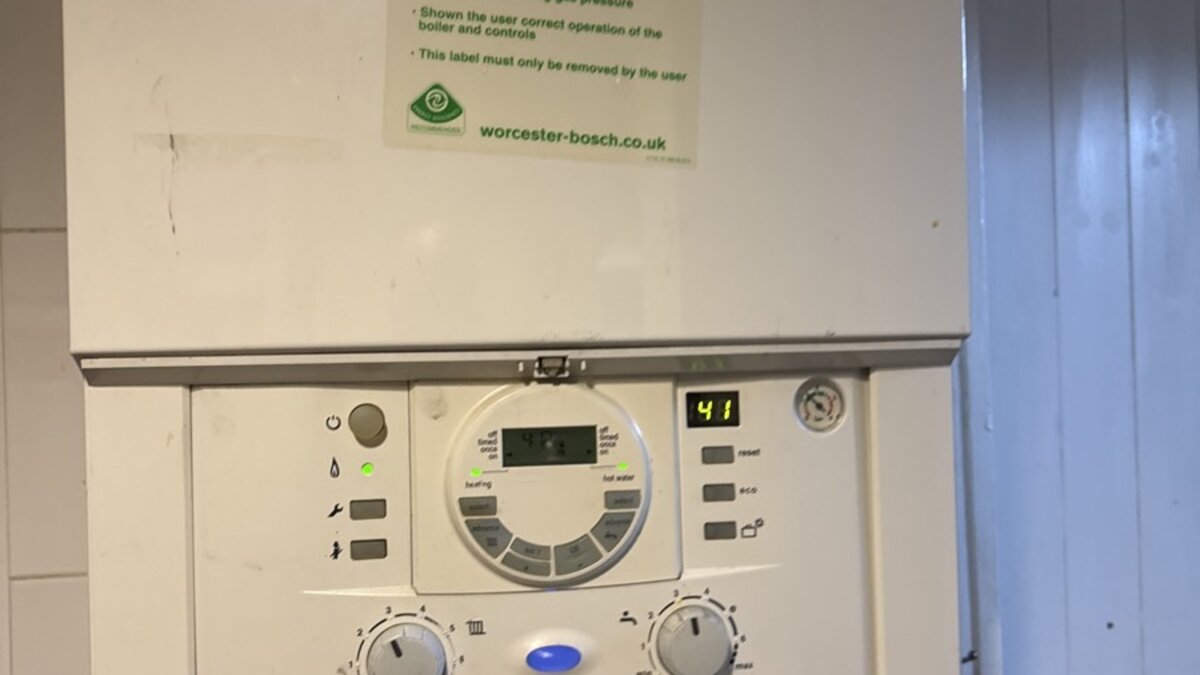
A previous diagnostic visit under reference JOB-158019 had identified the cause of the symptoms: a leaking flow sensor and associated turbine adaptor. The boiler was a Worcester-Bosch Greenstar CDi Classic — one of the most widely installed combination boilers in the UK domestic market. The tenant had been placing a bucket beneath the boiler to catch the drip, and the system was suffering from very low water pressure with no central heating output.
The home care provider — Hometree — instructed All Services 4U to return with the identified parts, supply and install them, and restore the boiler to full working order.
The Repair — Step by Step
Our heating engineer attended the property at 162 Southbridge Road, Croydon CR0 1DR, on 16 January 2026.
Boiler isolation. The boiler was isolated from the gas and electrical supplies before any work commenced. Safe isolation is a mandatory first step for all gas appliance repairs, ensuring no gas flow or electrical power to the appliance during component removal and installation.
Casing removal and access. The boiler casing was removed to access the internal components. The flow sensor and turbine adaptor are located within the domestic hot water circuit, typically accessible from the front or underside of the heat exchanger assembly.
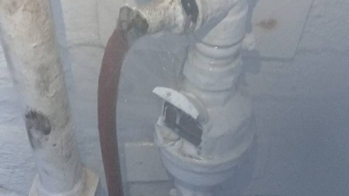
Removal of faulty components. The failed flow sensor and flow turbine adaptor were carefully removed. The connections — both hydraulic and electrical — were disconnected, and the surrounding area was inspected for water damage or corrosion that may have resulted from the leak.
Installation of new components. Genuine Worcester-Bosch replacement parts were installed. Using manufacturer-specified parts is essential for two reasons: mechanical compatibility (the tolerances, seal dimensions, and electrical connections must match the original design) and warranty compliance (non-genuine parts can void the remaining boiler warranty).
System repressurise. With the new components installed and all hydraulic connections sealed, the heating system was repressurised to the manufacturer’s specified operating pressure — typically between 1.0 and 1.5 bar for a cold system on a Worcester-Bosch combi boiler.
Testing and commissioning. The boiler was re-energised and tested through a full operational cycle. Hot water demand was simulated by opening a tap, confirming that the new flow sensor correctly detected the demand and signalled the PCB to fire the burner. The central heating circuit was activated to confirm that the boiler also responded to heating demand. System pressure was monitored to confirm no leaks from the new components or from any other point in the system.
Final verification. The system was confirmed leak-free, operating at stable pressure, with full heating and hot water output restored. The boiler was left in full working order.
Common Worcester-Bosch Greenstar Failure Modes
| Symptom | Likely Cause | Diagnostic Approach |
|---|---|---|
| Water dripping from boiler | Flow sensor seal failure; pressure relief valve discharge; heat exchanger crack | Trace drip to specific component |
| Low system pressure | Leak anywhere in system; expansion vessel failure; PRV weeping | Repressurise and monitor; pressure test if recurrent |
| No hot water, heating works | Flow sensor failure; diverter valve stuck | Check flow sensor signal; test diverter valve operation |
| No heating, hot water works | Diverter valve stuck; motorised valve fault (system boiler) | Check heating demand signal path |
| Boiler fires then shuts down | Overheat thermostat; blocked condensate; fan fault | Check error code on display |
| Boiler displays error code | Various — code-specific diagnosis required | Cross-reference with manufacturer fault code table |
| Kettling noise from boiler | Heat exchanger scale buildup; restricted flow | Descale heat exchanger; check system flow rate |