Integrated LED light fittings contain driver circuitry that converts mains voltage to the low-voltage DC supply required by the LED array. When these drivers fail, the most common outcome is simply that the light stops working. In less common but far more serious cases, the driver can overheat, leading to thermal breakdown of insulation materials, melting of plastic housings, and — in the worst scenario — ignition of surrounding materials in the ceiling void.
A ceiling void is a particularly dangerous location for a fire to originate. Voids are typically unmonitored, may contain other services (cabling, ductwork, pipework), and can allow fire and smoke to spread laterally across a wide area before detection. In a hospital environment, where patients may have limited mobility and where clinical services cannot simply be evacuated, the consequences of a ceiling void fire are amplified dramatically.
The Electricity at Work Regulations 1989 require that all electrical equipment be maintained so as to prevent danger. A burnt-out fitting that has already exhibited thermal failure meets the definition of dangerous equipment under Regulation 4, and any remaining fittings of the same type and age must be treated as a heightened risk. The previous diagnostic visit (L4L-792498) had already identified the full scope of failure, and this follow-on visit was commissioned specifically to carry out the remedial works.
The Health and Safety at Work Act 1974 places a general duty on the occupier to ensure, so far as is reasonably practicable, that the premises are safe and without risk to health. In a hospital setting, this duty extends to patients, staff, visitors, and anyone working in or passing through the affected area. The Regulatory Reform (Fire Safety) Order 2005 adds specific requirements for fire risk management in non-domestic premises, including the maintenance of electrical installations as potential ignition sources.
The Scope of Remedial Works
The remedial programme, defined following the diagnostic visit, comprised five specific tasks:
- Isolate the electrical supply to the affected lighting circuits to ensure safe working conditions.
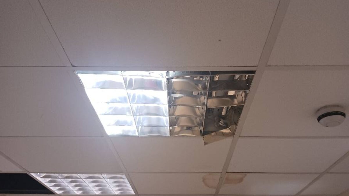
- Remove all five faulty integrated light fittings, including the unit that had burnt out above the ceiling.
- Dispose of all defective fittings and components safely in accordance with waste regulations.
- Install new, compatible integrated light fittings in all affected locations.
- Test all newly installed fittings and verify full lighting operation throughout the premises.
Each task carried its own technical and compliance requirements, and the sequence was critical — safe isolation must precede any physical work, and testing must follow installation before the circuits are returned to service.
Safe Isolation and Assessment
The engineer’s first action on arrival was to establish safe isolation of the affected lighting circuits at the distribution board. This is a non-negotiable first step in any electrical repair, governed by BS 7671 and reinforced by the Electricity at Work Regulations 1989. The safe isolation procedure involves identifying the correct circuit(s) at the distribution board, switching off and locking off the relevant circuit breaker(s), verifying that the circuit is dead at the point of work using an approved voltage indicator (which must itself be proved before and after use), and displaying warning notices where appropriate.
In a hospital environment, the engineer must also coordinate with the facilities management team to ensure that isolation does not affect adjacent clinical or critical areas. Power distribution in healthcare premises is often more complex than in standard commercial properties, with separate essential and non-essential supplies, and isolation of the wrong circuit could have patient safety implications.
Removal and Disposal
With safe isolation confirmed, the five faulty fittings were removed in sequence. The burnt-out unit in the ceiling void required particular care during extraction. A fitting that has experienced thermal failure may have damaged surrounding materials, and the engineer needed to assess the condition of the ceiling tile, any adjacent cabling, and the mounting surface before proceeding.
All five defective fittings were disposed of in accordance with the Waste Electrical and Electronic Equipment (WEEE) Regulations 2013, which classify light fittings as Category 5 waste (lighting equipment). WEEE regulations prohibit disposal of electrical equipment through general waste streams and require that it be collected separately and processed through approved treatment facilities to recover recyclable materials and safely handle any hazardous components.
Installation of Replacement Fittings
New, compatible integrated light fittings were installed in each of the five locations. Compatibility in this context means several things: the replacement fittings must match the physical dimensions and mounting configuration of the existing ceiling apertures, they must be electrically compatible with the circuit (correct voltage, appropriate current draw for the circuit protection), and they must carry the required certifications (CE/UKCA marking, appropriate fire ratings if installed in a fire-rated ceiling, and correct IP rating for the environment).
Each fitting was connected to the existing circuit wiring, with terminal connections made using the appropriate connector type and torqued correctly. In integrated LED fittings, the driver is typically built into the fitting body, so the connection is a straightforward permanent mains supply rather than the lamp holder arrangement used with replaceable-lamp fittings.
Testing and Verification
Before restoring power, the engineer conducted the standard sequence of post-installation electrical tests. Insulation resistance was measured to confirm that the new fittings had not introduced any fault to the circuit. Circuit protective conductor continuity was verified to confirm that the earth path was intact through each fitting.
With the circuits re-energised, each fitting was confirmed as operational, with correct light output and no flickering or abnormal behaviour. A final check at the distribution board verified that the circuit protection was stable under the full lighting load. The entire lighting system was confirmed as fully functional, safe, and compliant, with no faults identified post-installation.
Why Integrated Light Fittings Fail
Understanding the common failure modes of integrated LED fittings helps facilities managers recognise warning signs and plan replacement cycles. The table below summarises the principal causes of failure.
| Failure Mode | Cause | Warning Signs |
|---|---|---|
| Driver overheating | Poor ventilation, ambient temperature, manufacturing defect | Flickering, delayed start, burning smell |
| Capacitor degradation | Age, heat cycling, poor-quality components | Intermittent operation, audible buzzing |
| LED array failure | End of rated life, surge damage, thermal stress | Dimming, colour shift, partial illumination |
| Connection failure | Loose terminals, vibration, thermal expansion | Intermittent operation, arcing sounds |
| Catastrophic thermal failure | Sustained overheating leading to insulation breakdown | Burning smell, discolouration, visible damage |
In environments like hospital cafes, where fittings operate for extended hours (often 12-16 hours per day), the thermal and electrical stress on driver components is significantly higher than in standard commercial settings. This accelerated duty cycle should be factored into replacement planning.