Digital advertising and information screens are increasingly common in hospital cafes, waiting areas, and public concourses. Each screen requires a dedicated, reliable power supply — typically a standard 13A double socket outlet positioned behind the screen or advertising board to keep cabling concealed and the installation aesthetically acceptable.
While the end result appears simple — a socket behind a screen — the installation involves routing a new circuit or extending an existing one from the consumer unit to the socket location, which in this case meant running cabling between floors. The consumer unit was located upstairs, while the cafe and the socket location were on the ground floor. The cable route needed to be identified, cable management installed, and the circuit connected, tested, and certified before the socket could be put into service.
Under the Electricity at Work Regulations 1989, any new electrical installation must be constructed so as to prevent danger. The IET Wiring Regulations (BS 7671) provide the technical detail that gives effect to this legal requirement, setting out the standards for circuit design, cable selection, installation methods, and testing that must be met for the installation to be considered compliant.
Building Regulations Approved Document P classifies the installation of a new circuit as notifiable work. This means it must either be carried out by an electrician registered with a competent person scheme (such as NICEIC) or be notified to the local authority Building Control department before work commences. Registration with NICEIC allows All Services 4U’s electricians to self-certify notifiable work, avoiding the delay and cost of a separate Building Control inspection.
Circuit Design Considerations
The installation of a new double socket outlet requires design decisions that go beyond simply running a cable from A to B. The engineer must determine whether the socket will be served by a new dedicated circuit from the consumer unit or by extending (spurring from) an existing circuit. A new dedicated circuit provides the cleanest solution — it has its own overcurrent protection at the consumer unit, does not add load to an existing circuit, and can be independently isolated for maintenance. An extension from an existing circuit may be acceptable if the existing circuit has sufficient spare capacity and the number of existing spurs does not exceed the permitted limit.
In this case, the engineer accessed the upstairs consumer unit and the main electrical supply to safely connect the circuit as required. The cable was sized appropriately for the circuit’s protective device rating and the length of the cable run (which affects volt drop — the reduction in voltage over distance that BS 7671, Appendix 4, limits to 5% for lighting circuits and 5% for power circuits).
Cable selection also considers the installation method. Cable run in surface-mounted conduit has different current-carrying capacity ratings than cable in free air, in insulation, or in a wall chase. The engineer must apply the appropriate correction factors from BS 7671, Table 4A2, to ensure that the cable will not overheat under normal load conditions.
Cable Management and Aesthetics
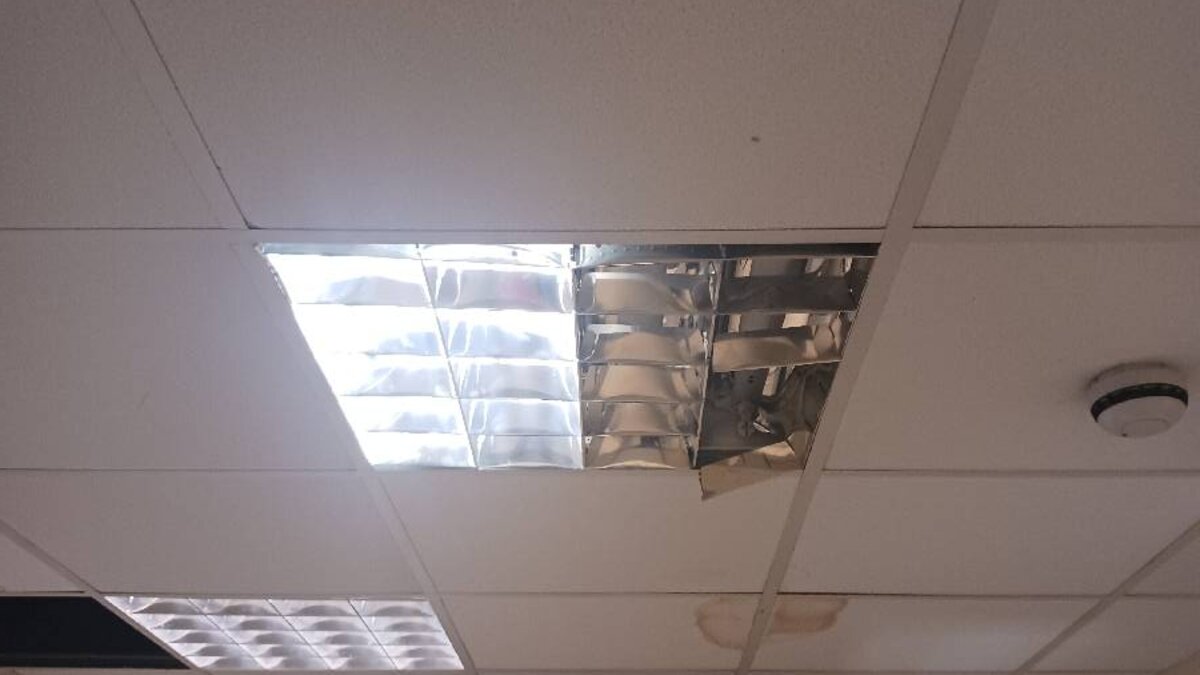
The specification required all cabling to be installed using white surface-mounted conduit. In a customer-facing environment like a hospital cafe, cable management is not merely a technical requirement — it directly affects the aesthetic standard of the space. Poorly routed or untidy cabling undermines the professional appearance of the premises and may attract negative comment from customers, staff, and hospital management.
Surface-mounted conduit offers several advantages in this context. It provides mechanical protection for the cable, reducing the risk of damage from impact, abrasion, or interference. It presents a clean, linear appearance that can follow the lines of walls and ceilings unobtrusively. It allows future inspection and modification of the cable without destructive access. And it satisfies the requirements of BS 7671, Chapter 52, for cable installation methods.
The conduit was installed in white to match the cafe’s existing wall finish, minimising visual impact. All joints, bends, and terminations were made using the appropriate conduit fittings to maintain the continuous protection of the cable along its entire route.
The Installation Process
The installation followed a structured sequence designed to ensure safety, compliance, and quality:
Step 1 — Safe Isolation and Access: The engineer identified the consumer unit location upstairs and established safe access to both the consumer unit and the cable route. Coordination with the cafe staff ensured that the installation could proceed without closing the cafe or disrupting service.
Step 2 — Cable Routing: The cable route was planned from the consumer unit downstairs to the socket location behind the advertising board. The route was selected to minimise conduit length, avoid crossing doorways or high-traffic areas, and follow building lines for aesthetic consistency. White surface-mounted conduit was installed along the entire route.
Step 3 — Circuit Connection: At the consumer unit, the new circuit was connected to an appropriately rated MCB (miniature circuit breaker). The circuit was also protected by an RCD (residual current device) — a requirement under BS 7671 for all socket outlet circuits in most installations. The combination of MCB and RCD protection (or an RCBO combining both functions) provides both overcurrent and earth fault protection.
Step 4 — Socket Installation: The double socket outlet was installed in the agreed position behind the advertising board. The socket was mounted securely, with the faceplate level and aligned. The cable was terminated at the socket with conductors correctly stripped, positioned, and tightened in the terminals.
Step 5 — Testing: Full electrical testing was carried out in accordance with BS 7671, Chapter 61. The tests included continuity of protective conductors, insulation resistance, polarity verification, earth fault loop impedance, prospective fault current, and RCD operation. These tests collectively confirm that the circuit is safe, that protective devices will operate within required disconnection times, and that the installation meets the standards required for certification.
Step 6 — Certification: An Electrical Installation Certificate (EIC) was issued, documenting the design, construction, and verification of the new circuit. The EIC is the formal record that the installation complies with BS 7671 and is signed by the designer, installer, and person responsible for inspection and testing. For notifiable work carried out by a NICEIC-registered contractor, the certificate also serves as the Building Regulations compliance notification.
Testing and Verification in Detail
Post-installation testing is not a formality — it is the process by which the engineer confirms that every aspect of the installation meets the required standard. The key tests and their purposes are detailed below.
| Test | Purpose | Acceptable Result |
|---|---|---|
| Continuity of protective conductors | Confirms earth path is intact from socket to consumer unit | Low resistance (typically under 1 ohm) |
| Insulation resistance | Confirms no breakdown of cable insulation | Minimum 1 megohm (typically much higher) |
| Polarity | Confirms line, neutral, and earth correctly connected | Correct at all points |
| Earth fault loop impedance (Zs) | Confirms protective device will trip within required time | Within tables in BS 7671 for device type/rating |
| Prospective fault current (Ipf) | Confirms protective device can safely interrupt maximum fault | Within device breaking capacity |
| RCD operation | Confirms RCD trips at correct current and speed | Trip at rated current within 300ms; at 5x within 40ms |
All tests returned satisfactory results, and the socket was confirmed as fully operational with no faults identified.
Common Considerations for New Socket Installations in Commercial Premises
Facilities managers and property operators who need new socket outlets installed should be aware of the key factors that affect the scope and cost of the work. The table below summarises the most common variables.
| Factor | Impact | What to Consider |
|---|---|---|
| Distance from consumer unit | Affects cable length, volt drop, and cable sizing | Longer runs may require larger cable cross-section |
| Floor-to-floor routing | Increases complexity if socket and CU are on different levels | Fire stopping may be required at floor penetrations |
| Cable management method | Surface conduit, trunking, or concealed in walls | Customer-facing areas typically require surface conduit or trunking |
| Circuit type (new vs. spur) | New circuit requires spare way at consumer unit | If no spare ways, CU upgrade may be required |
| Fire-rated construction | Penetrating fire-rated walls or floors requires fire stopping | Must be documented and compliant with Building Regs Part B |
| Hospital/healthcare environment | Additional coordination with estates/FM team | May require permit to work, out-of-hours working, or infection control measures |